Saturday, February 15, 2020

Turbine Flowmeter


This flow meter is named so as it measures flow by counting the rotation of a turbine that is positioned in the flow line. The fluid flowing through the pipe makes the blades of turbine rotate at a speed that is proportional to the flow velocity of the fluid. The number of revolutions is monitored by either a gear train or by a magnetic or optical pick-up.
The reader or a “pick-up” is installed perpendicular to the rotor. Two types of pick-up assemblies are commonly used: magnetic pick-up and no drag pick-up.

The magnetic pick-up consists of a permanent magnet with a coil wrapped around the magnet. When the turbine blades cut through the magnetic field, an alternating current, the frequency of which is proportional to the flow, is induced in the coil.
The no drag pick-up consists of an oscillator that transmits a high-frequency carrier wave to the coil of the pick-up. The rotation of the turbine modulates the carrier wave depending on the velocity of the rotor. In both cases pulses proportional to the flow are produced.


Every turbine flow meter is characterized by the K-factor, a coefficient that for a specific flow of a particular fluid shows how many pulses per liter are generated by the flow meter.
The K-factor can be calculated from:
K = 60*f/Qv
where
QV à the flow [liter/minute]
f à frequency [pulse/s]
Kà K-factor [pulse/liter].


Ideally, the value of K-factor should be constant i.e. relationship between the meter output and the flow rate should be linear. In reality, however, the driving torque of the fluid on the blade is
balanced by the influence of viscous, frictional and magnetic drag effects.

Since these vary with the flow rate, the shape of the K-factor curve depends on
viscosity, flow rate, bearing design, blade edge sharpness, blade roughness and the nature of
the flow profile at the turbine leading edge. In practice, all these influences have differing
effects on the meter linearity and thus all turbine meters, even from the same manufacturing
batch, should be individually calibrated.

The linear relationship of the K-factor is confined to a flow range of about 10:1 – sometimes
extending up to 20:1.

At low flows, the poor response of the meter is due to turbine rotor bearing friction, the effect of fluid viscosity and magnetic drag on the rotor due to the use of a magnetic pick-up. The humping section of the curve flattens as the viscosity decreases – with resultant increase in accuracy.

Practical installation

-The turbine flow meter requires equalization pipes at upstream and downstream sides of the instrument. The length of the horizontal pipe segment on both sides depends on the flow conditions. As a rule of thumb equalization pipe of 10D upstream and one of 5D downstream is recommended.

– The accuracy of the instrument is strongly influenced by the quality of the blades and the friction of the rotor against its axis.

– Inertia of the rotor can greatly influence the response time, especially when dealing with gases.
– To perform the digital-to-analog conversion, a frequency-to-voltage converter can be used, which transforms the pulses into a standard electrical signal.

– To stop any contamination that might block the turbine, a filter can be placed in front of the turbine flow meter if desired.

– Providing a bypass is efficient for continuous processes as it allows the replacement and cleaning of the flow meter (and of the filter) without interrupting the process.

Characteristics

Advantages

-          An extensive selection of ranges is available, for gases as well as for liquids.

-          A high level of accuracy, (0.2-0.3%), is attainable under specific circumstances because of the digital output.

-          Excellent repeatability (± 0.05 %).

-          Wide rangeability up to 20:1

-          Wide range of temperature applications from -220 to 600 °C

-          Measurement of non-conductive liquids.

-          Suitable for very low flow rates.

Disadvantages

-          Very sensitive to wear, especially with highly contaminated fluids and at high speeds.

-          Linear only in a limited area, which reduces the measuring range.

-          Not suitable for high viscous fluids.

-          Viscosity must be known.

-          10 diameter upstream and 5 diameters downstream of straight pipe is required.

-          Not effective with swirling fluids.

-          Only suitable for clean liquids and gases.

-          Relatively expensive.

Wednesday, February 5, 2020

Voltage references


The ability of a voltage reference or regulator to maintain a constant output under varying external conditions is characterized in terms of performance parameters such as line and load regulation, and the thermal coefficient. In the case of voltage references, output noise and long-term stability are also significant.


Line and Load Regulation
Line regulation, also called input, or supply regulation, gives a measure of the circuit’s ability to maintain the specified output under varying input conditions.


where Vo is the output change resulting from a change ∆Vi at the input. Line regulation is expressed in millivolts or microvolts per volt.


Load regulation gives a measure of the circuit’s ability to maintain the specified output voltage under varying load conditions.

Temperature Coefficient
The temperature coefficient of output voltage gives a measure of the circuit’s ability to maintain the specified output voltage Vo under varying thermal conditions.
It is usually expresses in mV/C.
Besides line and load regulation, thermal stability is the most critical performance requirement of voltage references due to the tendency of IC components to be strongly affected by change in temperature. Consider the silicon pn junction, which forms the basis of diodes and BJTs. Its forward-bias voltage VD and current ID are related as
where VT is the thermal voltage and Is the saturation current.
where k =1.38×10⁻²³ J/K is known as Boltzmann’s constant, q = 1.602 x 10⁻¹⁹ C, T is absolute temperature.

TC = VT/T = k/q = 0.086 mV/C
Temperature coefficient for diode forward voltage drop VD is -2.1 mV/ C.
Two types of voltage references are popular - Zener voltage reference and Bandgap reference.

Zener Voltage Reference

A zener diode is widely used as a voltage reference. While true zener breakdown occurs below 5V, avalanche breakdown occurs at higher voltages and has a positive temperature coefficient. Zener breakdown truly has negative temperature coefficient but nowadays avalanche breakdwon is referred to as zener breakdown only.

A combination of normal PN diode with negative temperature coefficient is used to compensate for temperature instability as shown below.

However to get maximum temperature compensation, odd values of output voltage is produces like 4.7, 5.3, 6.2V etc.

As Zener to avalance transition occur at 5.6 volt (and we use avalanche diode as voltage reference), a input voltage higher than 6.2V (5.6+VD) is required.
                       
  
Bandgap voltage reference

For circuits which are powered by low voltage supply, bandgap reference offers an exciting choice. They can offer much lower voltage output as they utilize PN junction bandgap voltage which is 1.2V for Silicon.

The value of VT is 0.086mV/C and it has positive temperature coefficient. This voltage can be used to compensate temperature related variation of VBE by amplifying the value to +2mV/C.

This is the scheme behind Bandgap reference.

The actual circuit of a bandgap reference may look as below.


Thursday, January 9, 2020

Pipe Threads- NPT vs BSP threads


Pipe is a hollow structure designed to provide an enclosed pathway for fluids to flow, usually
manufactured from cast metal or plastic. This section discusses some common methods for joining pipes and pipe ends with instruments together.


Tapered thread pipe fittings

·         Thread fittings are more preferred for smaller pipe sizes.

·         A very common design of threaded pipe fitting is the tapered pipe thread design.

·         The intent of a tapered thread is to allow the pipe and fitting to “wedge” together when engaged, creating a joint that is both mechanically rugged and leak-free.


Several different standards exist for tapered-thread pipe fittings. For each standard, the angle of
the thread is fixed, as is the angle of taper. Thread pitch (the number of threads per unit length) varies with the diameter of pipe fitting.

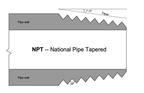
The most common tapered thread standard for general-purpose piping is the NPT, or National Pipe Taper design. NPT threads have an angle of 60° and a taper of 1°47’.


NPT pipe threads must have some form of sealant applied prior to assembly to ensure pressure tight sealing between the threads. Teflon tape and various liquid pipe “dope” compounds work well for this purpose. Sealants are necessary with NPT threads for two reasons: to lubricate the male and female pieces (to guard against galling the metal surfaces), and also to fill the spiral gap formed between the root of the female thread and the crest of the male thread.


Another tapered-thread standard is the BSPR, or British Standard Pipe Tapered. BSPT threads have a narrower thread angle than NPT threads (55° instead of 60°) but the same taper angle 1°47’.


Parallel-thread pipe fittings

·         One popular parallel-thread pipe standard is the BSPP, or British Standard Pipe Parallel.

·         Like the BSPT (tapered) standard, the thread angle of BSPP is 55°.

·         Sealing is accomplished by means of an O-ring which compresses against the shoulder of the matching female fitting:


Difference between coaxial line and waveguide

Coaxial CableWave-guide
1.It consists of center conductor and outer conductor.Waveguide consists of single metallic walls acting as conductor. There is no center conductor in the waveguide.
2.The fundamental or dominant mode wave in a coaxial line is TEM.TEM wave can not propagate through it. Wave transmission takes place using TE or TM modes.
3.There is no concept of cutoff frequency.Each waveguide has a finite cut-off frequency.
4.The coaxial lines have PTFE as di-electric and have relatively higher loss.As waveguide is air filled there will be less loss compare to coaxial line.
5.The power handling ability of coaxial-cable is relatively lesser.Waveguide can handle higher power compared to coaxial cable because waveguide is filled with air as dielectric and air has higher break down voltage.
6.The bandwidth of coaxial line is broad.The bandwidth of waveguide is smaller.

Monday, January 6, 2020

Analog Voltage Divider or voltage division or voltage ratio circuit using Op-amp

Operational amplifier is a powerful tool to perform different mathematical operations on analog signals. In this post we will discuss about circuit to implement voltage ratio or voltage division using operational amplifiers.

Let us design a circuit to implement the following expression

Vout = (V1-Vref)/ (V2-Vref)

We will use the property of "logarithm" to implement division. And voltage difference circuit to offset Vref.
We know that log(A) - log(B) = log(A/B).
In our problem,
A = V1 - Vref
B = V2 - Vref

First stage is a difference amplifier which subtract Vref from V1 and V2 respectively. This gives us voltage Va and Vb.
The second stage performs logarithm of input voltage to obtain Va' and Vb'.

The final output voltage will be Va'-Vb'.


By setting suitable value of gain factor (-kT/q) and resistance ratio in previous stages, we can get the required expression of voltage division at the out.


Friday, January 3, 2020

I to V conversion. Convert 4-20mA to 1-5V, 0-5V, 1-10V, 0-10V

Current to Voltage converters or I to V converters as they are generally known are popular in process control applications where we need to interface output from transmitters to a data-acquisition system. Transmitter output are generally in 4 to 20 mA format which has to be converted to voltage form before feeding to a DAQ device.
In this post I will discuss about different circuits which convert 4-20 mA signals to 1-5V, 0-5V, 1-10 V and 0-10V form.
  • 4-20mA to 1-5VDC
This conversion can be simply implemented by using a precision 250 Ohm resistor.

The first circuit is a simple implementation of I-V converter. The value of resistor R is 250Ohm.
For 4 mA current, the voltage drop is 4*250 = 1V,
For 20 mA current, the voltage drop is 20*250 = 5V.

This circuit can load the current source (transmitter output DAC) when DAQ device or measuring meter is connected across the resistor causing error in measurement. By adding a buffer/ voltage follower, we are adding very input impedance across the resistor. This protects the source from getting loaded and provide accurate measurement of voltage drop.

One very common configuration of I-V converter using Op-amp is as below. The load is floated in this case.
At the output stage, inverting op-amp is used to get 1-5Volt.

  • 4-20 mA to 0-5 VDC
Just by changing the resistor value to 312.5 Ohm and adding an adder circuit with -1.25 V offset voltage, we can convert 4-20 mA to 0-5 VDC. The schematic is shown below.

  • 4-20 mA to 0-10 VDC
The circuit is same as above, only the value of resistor is changed to 625 Ohm and offset voltage is set to -2.5 VDC.

There is one more way of getting 0-10V. Here we will use 0-5VDC circuit with slight modifications. The op-amp is used in non-inverting configuration to provide a gain of 2.
  • 4-20 mA to 1-10 VDC


RF PCB Design-Part 3: Transmission Line Design

Transmission line design is fundamental in RF PCB design for maintaining signal integrity and minimizing power loss at high frequencies. A t...