Thursday, January 9, 2020

Pipe Threads- NPT vs BSP threads


Pipe is a hollow structure designed to provide an enclosed pathway for fluids to flow, usually
manufactured from cast metal or plastic. This section discusses some common methods for joining pipes and pipe ends with instruments together.


Tapered thread pipe fittings

·         Thread fittings are more preferred for smaller pipe sizes.

·         A very common design of threaded pipe fitting is the tapered pipe thread design.

·         The intent of a tapered thread is to allow the pipe and fitting to “wedge” together when engaged, creating a joint that is both mechanically rugged and leak-free.


Several different standards exist for tapered-thread pipe fittings. For each standard, the angle of
the thread is fixed, as is the angle of taper. Thread pitch (the number of threads per unit length) varies with the diameter of pipe fitting.

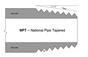
The most common tapered thread standard for general-purpose piping is the NPT, or National Pipe Taper design. NPT threads have an angle of 60° and a taper of 1°47’.


NPT pipe threads must have some form of sealant applied prior to assembly to ensure pressure tight sealing between the threads. Teflon tape and various liquid pipe “dope” compounds work well for this purpose. Sealants are necessary with NPT threads for two reasons: to lubricate the male and female pieces (to guard against galling the metal surfaces), and also to fill the spiral gap formed between the root of the female thread and the crest of the male thread.


Another tapered-thread standard is the BSPR, or British Standard Pipe Tapered. BSPT threads have a narrower thread angle than NPT threads (55° instead of 60°) but the same taper angle 1°47’.


Parallel-thread pipe fittings

·         One popular parallel-thread pipe standard is the BSPP, or British Standard Pipe Parallel.

·         Like the BSPT (tapered) standard, the thread angle of BSPP is 55°.

·         Sealing is accomplished by means of an O-ring which compresses against the shoulder of the matching female fitting:


Difference between coaxial line and waveguide

Coaxial CableWave-guide
1.It consists of center conductor and outer conductor.Waveguide consists of single metallic walls acting as conductor. There is no center conductor in the waveguide.
2.The fundamental or dominant mode wave in a coaxial line is TEM.TEM wave can not propagate through it. Wave transmission takes place using TE or TM modes.
3.There is no concept of cutoff frequency.Each waveguide has a finite cut-off frequency.
4.The coaxial lines have PTFE as di-electric and have relatively higher loss.As waveguide is air filled there will be less loss compare to coaxial line.
5.The power handling ability of coaxial-cable is relatively lesser.Waveguide can handle higher power compared to coaxial cable because waveguide is filled with air as dielectric and air has higher break down voltage.
6.The bandwidth of coaxial line is broad.The bandwidth of waveguide is smaller.

Monday, January 6, 2020

Analog Voltage Divider or voltage division or voltage ratio circuit using Op-amp

Operational amplifier is a powerful tool to perform different mathematical operations on analog signals. In this post we will discuss about circuit to implement voltage ratio or voltage division using operational amplifiers.

Let us design a circuit to implement the following expression

Vout = (V1-Vref)/ (V2-Vref)

We will use the property of "logarithm" to implement division. And voltage difference circuit to offset Vref.
We know that log(A) - log(B) = log(A/B).
In our problem,
A = V1 - Vref
B = V2 - Vref

First stage is a difference amplifier which subtract Vref from V1 and V2 respectively. This gives us voltage Va and Vb.
The second stage performs logarithm of input voltage to obtain Va' and Vb'.

The final output voltage will be Va'-Vb'.


By setting suitable value of gain factor (-kT/q) and resistance ratio in previous stages, we can get the required expression of voltage division at the out.


Friday, January 3, 2020

I to V conversion. Convert 4-20mA to 1-5V, 0-5V, 1-10V, 0-10V

Current to Voltage converters or I to V converters as they are generally known are popular in process control applications where we need to interface output from transmitters to a data-acquisition system. Transmitter output are generally in 4 to 20 mA format which has to be converted to voltage form before feeding to a DAQ device.
In this post I will discuss about different circuits which convert 4-20 mA signals to 1-5V, 0-5V, 1-10 V and 0-10V form.
  • 4-20mA to 1-5VDC
This conversion can be simply implemented by using a precision 250 Ohm resistor.

The first circuit is a simple implementation of I-V converter. The value of resistor R is 250Ohm.
For 4 mA current, the voltage drop is 4*250 = 1V,
For 20 mA current, the voltage drop is 20*250 = 5V.

This circuit can load the current source (transmitter output DAC) when DAQ device or measuring meter is connected across the resistor causing error in measurement. By adding a buffer/ voltage follower, we are adding very input impedance across the resistor. This protects the source from getting loaded and provide accurate measurement of voltage drop.

One very common configuration of I-V converter using Op-amp is as below. The load is floated in this case.
At the output stage, inverting op-amp is used to get 1-5Volt.

  • 4-20 mA to 0-5 VDC
Just by changing the resistor value to 312.5 Ohm and adding an adder circuit with -1.25 V offset voltage, we can convert 4-20 mA to 0-5 VDC. The schematic is shown below.

  • 4-20 mA to 0-10 VDC
The circuit is same as above, only the value of resistor is changed to 625 Ohm and offset voltage is set to -2.5 VDC.

There is one more way of getting 0-10V. Here we will use 0-5VDC circuit with slight modifications. The op-amp is used in non-inverting configuration to provide a gain of 2.
  • 4-20 mA to 1-10 VDC


Modbus and OPC comparison Table

  Modbus vs OPC Comparison between Modbus and OPC Feature Modbus OPC (OLE f...