There are many
applications where it is required for one system to have no direct electrical
connection with the other system. Such isolation is called Galvanic isolation. This is necessary to avoid the
possibility of dangerous voltages or currents from one half of the system causing
damage to the other, or to break ground loop. Such a system is said to be
"isolated", and the arrangement that passes a signal without galvanic
connections is known as an isolation barrier.
The protection of an
isolation barrier works in both directions. The common applications where a sensor
may accidentally encounter high voltages and the system it is driving must be
protected.
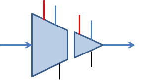
An isolation amplifier
provides dc isolation between input and output. It is used for the protection
of human life or sensitive equipment in those applications where high-voltage
transients or power leakage are possible. An isolation amplifier consists of two electrically isolated
stages. The input stage and the output stage are separated from each other by
an isolation barrier so that a signal must be processed in order to be coupled
across the isolation barrier.
Complete isolation of
two electrical system include- signal isolation, power isolation.
Application
·
To protect human operators,
·
To protect low-voltage circuitry from
high voltages,
·
To improve noise immunity,
·
To reject common mode voltage,
·
To eliminate ground loop,
·
To handle ground potential differences
between communicating subsystems.
Types
of signal isolation
1.
Optical Isolation
2.
Transformer/ magnetic/ inductive isolation
3.
Capacitive isolation
Some isolation
amplifiers use optical coupling or transformer coupling to provide isolation
between the stages. However, many modern isolation amplifiers use capacitive
coupling for isolation. Each stage has separate supply voltages and grounds so
that there are no common electrical paths between them.
The most common
isolation amplifiers use transformers, which exploit magnetic fields, and
another common type uses small high voltage capacitors, exploiting electric
fields.
Optical
isolation
Optoisolators, which
consist of an LED and a photodiode/ phototransistor, provide isolation by using
light. Optical isolators are fast and cheap, and can be made with very high
voltage ratings (4 -7 kV is one of the more common ratings), but they have poor
analog linearity, and are not usually suitable for direct coupling of precision
analog signals.
Analog optocoupler
The analog optocouplers
can be used to isolate analog signals in a wide variety of applications that
require good stability, linearity, bandwidth and low cost. HCNR200/201 is
popular analog optocoupler. Their circuit schematic is as shown below.

The figure below shows the working circuit of analog voltage isolator using HCNR200.

The ratio of R3/R1 can be selected to provide amplification to the input signal. The ground for input stage (left side) must be separated from ground for output stage (right side). Separate set of power supplies or isolated DC-to-DC converters can be used for this purpose.
Digital optocoupler
The classic digital
isolator is the LED/transistor opto-isolator. It can provide isolation upto
10kV or more. Higher speed couplers incorporate an active receiver circuit with
a logic-level output.

Transformer isolation
Electromagnetic isolators such as small signal transformers are useful for AC signal isolation. Transformers
like audio transformer have their primary and secondary sides
isolated which can be used for different audio signal isolation. Another most common use is in network
hardware or Ethernet section. Pulse
transformers are used to isolate the external wiring with internal
hardware. Even telephone lines are used transformer based signal isolators.
But, as transformers are isolated by electromagnetically, it only works with
AC.
Transformers are
capable of analog accuracy of 12-16 bits and bandwidths up to several hundred
kHz, but their maximum voltage rating rarely exceeds 10 kV, and is often much
lower.
Capacitive isolation
The least popular method for isolating circuits is by
using capacitors. Due to poor efficiency and dangerous failure outcomes
this is no longer preferred. Capacitors block DC and allow passing a
high-frequency AC signal. Due to this property, the capacitor is used as
isolators in designs where DC currents of two circuits need to be blocked but
still allowing high frequency data transmission.
Capacitive-coupled
isolation amplifiers have lower accuracy, perhaps 12-bits maximum, lower
bandwidth, and lower voltage ratings—but they are low cost.

Characteristics
·
Linearity- It is desirable that the
relation between input and output signal is linear. Modern isolation techniques
make it possible to achieve linearity as low as 0.01%.
·
Isolation voltage- It is the maximum voltage
on side that can be withstand by the isolation barrier between two stages.
Beyond isolation voltage, the barrier breaks down.
·
Bandwidth- It is the frequency range of
input signal that can be coupled at the output without significant attenuation.
·
Transfer gain- Ratio of output signal to
input signal.


No comments:
Post a Comment