Working Principle
The
working principle of the ultrasonic flow meter is based on the transmission
of ultrasonic waves in a medium. One or more ultrasonic transmitting-receiving pairs are mounted in or on the pipe, diametrically opposite to each other. The first pair is placed slightly more downstream than the second pair, so they make a certain angle with the pipe longitudinally.
of ultrasonic waves in a medium. One or more ultrasonic transmitting-receiving pairs are mounted in or on the pipe, diametrically opposite to each other. The first pair is placed slightly more downstream than the second pair, so they make a certain angle with the pipe longitudinally.
The
main idea behind the principle is the detection of frequency or phase shift
caused by flowing medium. The effective velocity of sound in a moving medium is
equal to the velocity of sound relative to the medium plus the velocity of the
medium with respect to the source of the sound. Thus, a sound wave propagating
upstream will have a smaller effective velocity, and the sound propagating
downstream will have a higher effective velocity. Because the difference
between the two velocities is exactly twice the velocity of the medium, measuring
the upstream–downstream velocity difference allows us to determine the velocity
of the flow.
Types of Ultrasonic
Flowmeters
There
are various types of ultrasonic flowmeters in use for discharge measurement:
(1) Transit time
This
type of ultrasonic flowmeter makes use of the difference in the time for a
sonic pulse to travel a fixed distance, first against the flow and then in the
direction of flow. Transmit time flowmeters are sensitive to suspended solids
or air bubbles in the fluid.

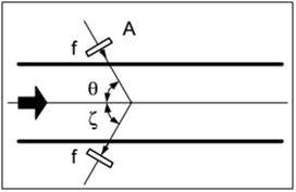
Figure
above shows two ultrasonic generators positioned on opposite sides of a pipe of
flow. Piezoelectric crystals are usually employed for that purpose. Each crystal
can be used for either the generation of the ultrasonic waves or for receiving
the ultrasonic waves. Two crystals are separated by distance D and
positioned at angle ‘ф’ with respect to flow. The transit time of sound
between two transducers A and B can be found through the average fluid velocity
v:

where
c is the velocity of
sound in the fluid. The velocity v
is the flow velocity averaged along the path of the ultrasound. By taking
the difference between the downstream and upstream velocities, we find
(2) Doppler frequency shift
This
type is more popular and less expensive, but is not considered as accurate as
the transit time flowmeter. It makes use of the Doppler frequency shift caused
by sound reflected or scattered from suspensions in the flow path and is
therefore more complementary than competitive to transit time flowmeters.
This technique is
more popular in so-called “clamp-on” meters. The Doppler effect occurs with
sound as well as electromagnetic waves. When a source or receiver moves in a
wave medium, the frequency at the receiver will differ from the frequency at
the transmitter. The frequency increases with a movement towards the source and
it decreases with a movement away from the source. This is caused by the
constant velocity of the wave in the medium. If all velocities in the same direction
are counted positively, we can describe the Doppler effect as follows:
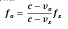
Where
fo:
observed frequency for movement
fs:
frequency of the source in rest
c: transmission
velocity in the medium
vo:
velocity of the observer with respect to the medium
vs:
velocity of the source with respect to the medium
During the
measurement the source (transmitting crystal) and the observer (receiving
crystal) are fixed and the fluid is moving. The transmitted signal is only
detected if dispersed by moving fluid particles. These particles can be solids
or small gas pockets. The Doppler technique only works in liquids that contain
enough solids or gas pockets.
The Doppler frequency shift is:

For the Doppler
flow measurements, continuous ultrasonic waves can be used. Figure below shows
a flowmeter with a transmitter–receiver assembly positioned inside the flowing
stream. Here angles are zero. That differential is defined as


Installation
requirement:
In general
acoustic flow meters need no special requirements regarding installation on or
in the process pipe:
- A vibration-free location is recommended
especially when applying the Doppler type flowmeter, as vibrations cause false
signals which may fool the electronics.
-
Similar
to most flow meters, the measuring pipe must be completely filled with the
fluid.
-
A
well-developed flow profile is absolutely required for a reliable and accurate
measurement. That is why equalization pipes 10 D in front of and 5 D behind the
meter are recommended to obtain the given level of accuracy (2%).
-
Pilot
valves closely behind the flow meter negatively influence the measurement,
especially when cavitation or supersonic velocities occur.
Characteristics:
–
No
pressure loss in the pipe.
–
It
is possible to measure without making contact with the fluid (“clamp-on”).
–
Only
useful for liquids that are acoustically transparent.
–
A
small, but not excessive amount of contamination of the liquid is necessary for
the Doppler effect. The time-of-flight principle needs as little pollution as
possible.
–
Difficult
for small diameters, especially when using the time-of-flight principle.
–
For
the time-of-flight difference meter the turndown can amount to 1:1,000 and an
accuracy level from 1% to 2.5% is possible. For the Doppler type meter the
turndown can amount to 1:3,000 with an accuracy level from 2% to 5%.
–
Individual
calibration is needed for every medium.
–
Using
the Doppler effect, the reading depends on the flow profile.
–
Accuracy
levels up to 1% are possible (not when using clamp-on realizations).
–
At
present it is also possible to ultrasonically measure the flow of gases, steam and
even high-temperature steam.
Questions
GATE 2014
A transit time ultrasonic flowmeter uses a pair of ultrasonic transducers placed at 45° angle, as shown in the figure.
 The inner diameter of the pipe is 0.5 m. The differential transit time is directly measured using a clock of frequency 5 MHz. The velocity of the fluid is small compared to the velocity of sound in the static fluid, which is 1500 m/s and the size of the crystals is negligible compared to the diameter of the pipe. The minimum change in fluid velocity (m/s) that can be measured using this system is_________.
GATE 2018
T he average velocity v of flow of clear water in a 100 cm (inner) diameter tube is measured
using the ultrasonic flow meter as shown in the figure. The angle ø is 45 degree. The measured
transit times are t1 = 0.9950 ms and t2 = 1.0000 ms. The velocity v (in m/s) in the pipe is (up
to one decimal place) ___.
GATE 2014
A transit time ultrasonic flowmeter uses a pair of ultrasonic transducers placed at 45° angle, as shown in the figure.

GATE 2018
T he average velocity v of flow of clear water in a 100 cm (inner) diameter tube is measured
using the ultrasonic flow meter as shown in the figure. The angle ø is 45 degree. The measured
transit times are t1 = 0.9950 ms and t2 = 1.0000 ms. The velocity v (in m/s) in the pipe is (up
to one decimal place) ___.


No comments:
Post a Comment