Monday, September 23, 2024

Getting Started with Codesys v3.5 and Wago PFC200 (750-8212)


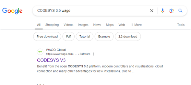
Step 1: Search for Codesys v3.5 in any search engine.


Step 2: When you click on the link, it redirects you to following page. Click on the download button. It will redirect you to a new webpage with Codesys v 3.5 descriptions.


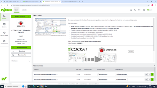
Step 3: Click on Open Page link, which open a new webpage.


Step 4: User can download the software along with dependencies as a bundle download or selecting individual dependency as per his/her requirement.


Step 5: Click on Codesys 3.5 setup file to initiate installation.


Once installation is complete, launch the Codesys to check if installation is correct.

After this, you have to install Wago Licensing, Wago Solution Builder, Wago codesys Download Server, Wago Device and Libraries which are downloaded in Step 4 as a bundle.

Step 6: Again Launch Codesys 3. Create a New Project from Basic Operations.


Create a standard project and then choose suitable Name and Location where you want to save the project file.


Once done, you have to select the Device and Programming Language from drop down menu.


I have selected 750-8212 as my PLC device and Ladder Logic Diagram as my programming language. You will see the device list only if Wago Device and Libraries are properly installed.


Selected target system is different from the connected device

Once you connect a Wago PFC 750-8212 device with PC and develop a ladder program, you will have to download the program into the PLC.

In some cases, it may display “selected target system is different from the connected device” error message. This happens due to firmware incompatibility between the codesys wago device library and PLC firmware. The user will have to update the firmware of the device in that case.


PLC Firmware update


In the softwares downloaded in Step-1, you will find Firmware also which needs to be uploaded to the PLC. The firmware can be uploaded using Wagoupload. WAGOupload is a stand-alone PC software for transferring, backing up and restoring PLC applications on WAGO 750 Series controllers.


Wednesday, January 3, 2024

Modbus and OPC comparison Table


Modbus vs OPC

Comparison between Modbus and OPC

Feature Modbus OPC (OLE for Process Control)
Definition Communication protocol Communication protocol and data exchange standard
Protocol Type Serial and Ethernet-based Can use various protocols, including TCP/IP
Topology Master/Slave Client/Server and Publish/Subscribe
Data Types Limited data types (e.g., integers, floats) Extensive data types (e.g., integers, floats, strings)
Complexity Simple and lightweight More complex and feature-rich
Flexibility Limited flexibility in terms of data format Highly flexible, supports complex data structures
Scalability Suitable for small to medium-scale systems Suitable for small to large-scale systems
Integration Widely used in industrial automation Common in industrial automation, more versatile
Interoperability Interoperability may be limited Emphasizes interoperability, supports multiple platforms
Vendor Neutrality Generally vendor-neutral Allows for vendor-specific implementations
Security Basic security features OPC UA provides advanced security features
Standards Open standard, but various versions exist Open standard with defined specifications (OPC UA)
Popular Versions Modbus RTU, Modbus TCP OPC DA (Data Access), OPC HDA (Historical Data Access), OPC UA (Unified Architecture)
Usage Common in simple industrial systems Used in a wide range of industrial automation scenarios

This table provides a high-level overview, and the choice between Modbus and OPC depends on specific project requirements and considerations.

Friday, December 29, 2023

Modbus vs OPC


OPC

  • OPC stands for OLE for Process Control. OPC is communicating software-to-software for operator display.
  • OPC is mostly a standard interface software between a driver, mostly for networks and device hardware, and also a databases, and the application display for example software of HMI/process visualization.
  • You use OPC between a hardware driver software (OPC server) and a process visualization software (OPC client) on a Windows computer, or another client such advanced control, statistics etc. If the server and client applications are in different computers they communicate across Ethernet.
  • OPC is principle within the environment of Windows to get data from the server I/O to other applications for example process control, soft alarms, graphics, trend, advanced control, auto tuning, statistical etc. anyway if the applications are implementing on the different or same computers.
  • OPC is not the finest option for interlock communication and closed loops between controllers. Because it is not completely deterministic or real-time.
  • For OPC you can browse the data, see what is available, without having to worry where it is located and in what data type. This makes it a whole lot easier to use. OPC runs on Windows operating system so OPC depends on the reliability of computers.
MODBUS
  • Modbus is communicating hardware-to-hardware for control.
  • Modbus/TCP is idyllic for interlock communication and closed loops between controllers.
  • It is all software driven and does not need any cards of scanner, Just RS-485 or RS-232.
  • You can use either Modbus, Profibus, or any other fieldbus for closed loop control.

  • Modbus/TCP is not the most excellent option for communications between computers or between applications software. It is because the Modbus/TCP simplicity comes from a lack of logical object structure and a standard data types.
  • Modbus breaks data down to the lowest feasible denominator. That’s why it can move to anywhere, but once it takes there it gets many user configuration attempt to plan registers Modbus back into names of parameter and group them rationally in objects and separating what all the types of data are thought to be after all has been changed to words of Modbus. For some parameters it is feasible, but with the great amount of information accessible in up to date systems it does not fly.
  • For Modbus you find data in registers. Every device use different registers, and if the device is programmable the registers will also be different for each application. Some devices use integers while other use floating point. Some devices use percentage while others use engineering unit. You need to refer to device documentation to find which information is in which register and what format is used. This is quite tedious. Making changes often create a lot of work.


Monday, December 11, 2023

Arduino interfacing with ADS1115 for high resolution analog measurement


To interface with the ADS1115 ADC and print data on an LCD using Arduino, you will need to do the following:

  1. Connect the ADS1115 to the Arduino using the I2C protocol. Connect the SDA and SCL pins of the ADS1115 to the corresponding pins on the Arduino (A4 and A5, respectively).

  2. Connect the LCD to the Arduino using the appropriate pins. This can vary depending on the specific LCD you are using, but typically involves connecting the LCD's data pins (D4-D7) to digital pins on the Arduino and connecting the RS, E, and RW pins to other digital pins.

  3. Include the necessary libraries in your Arduino sketch. You will need the Wire library for I2C communication and the LiquidCrystal library for controlling the LCD.

  4. In your sketch, initialize the ADS1115 and the LCD. This will involve setting up the I2C communication and configuring the ADC and the LCD for your specific needs.

  5. Continuously read the data from the ADS1115 and display it on the LCD. You can use the ADS1115 library to read the data from the ADC, and the LiquidCrystal library to write the data to the LCD.

Here's some example code to get you started:

#include <Wire.h> #include <Adafruit_ADS1015.h> #include <LiquidCrystal.h> #define ADS1115_ADDRESS 0x48 Adafruit_ADS1115 ads(ADS1115_ADDRESS); #define LCD_RS 12 #define LCD_EN 11 #define LCD_D4 5 #define LCD_D5 4 #define LCD_D6 3 #define LCD_D7 2 LiquidCrystal lcd(LCD_RS, LCD_EN, LCD_D4, LCD_D5, LCD_D6, LCD_D7); void setup() { Wire.begin(); ads.begin(); lcd.begin(16, 2); } void loop() { int16_t adc0, adc1, adc2, adc3; adc0 = ads.readADC_SingleEnded(0); adc1 = ads.readADC_SingleEnded(1); adc2 = ads.readADC_SingleEnded(2); adc3 = ads.readADC_SingleEnded(3); lcd.clear(); lcd.setCursor(0, 0); lcd.print("ADC0: "); lcd.print(adc0); lcd.setCursor(0, 1); lcd.print("ADC1: "); lcd.print(adc1); delay(500); }

This code initializes the ADS1115 and the LCD in the setup() function, and continuously reads the data from the ADC and displays it on the LCD in the loop() function. The ADC data is read using the readADC_SingleEnded() function, and the data is written to the LCD using the print() function of the LiquidCrystal library. You can modify this code to suit your specific needs, such as changing the ADC channels that are read, or adding additional LCD displays.


#include <Wire.h> #include <Adafruit_ADS1015.h> #include <LiquidCrystal.h> #define ADS1115_ADDRESS 0x48 Adafruit_ADS1115 ads(ADS1115_ADDRESS); #define LCD_RS 12 #define LCD_EN 11 #define LCD_D4 5 #define LCD_D5 4 #define LCD_D6 3 #define LCD_D7 2 LiquidCrystal lcd(LCD_RS, LCD_EN, LCD_D4, LCD_D5, LCD_D6, LCD_D7); void setup() { Serial.begin(9600); Wire.begin(); ads.begin(); lcd.begin(16, 2); } void loop() { int16_t adc0, adc1, adc2, adc3; adc0 = ads.readADC_SingleEnded(0); adc1 = ads.readADC_SingleEnded(1); adc2 = ads.readADC_SingleEnded(2); adc3 = ads.readADC_SingleEnded(3); lcd.clear(); lcd.setCursor(0, 0); lcd.print("ADC0: "); lcd.print(adc0); lcd.setCursor(0, 1); lcd.print("ADC1: "); lcd.print(adc1); Serial.print("ADC0: "); Serial.println(adc0); Serial.print("ADC1: "); Serial.println(adc1); delay(500); }

This code adds the Serial.begin() function to initialize serial communication at a baud rate of 9600. In the loop() function, the ADC data is read and displayed on the LCD as before, but it is also sent over serial using the Serial.print() and Serial.println() functions. This allows you to monitor the ADC data in real-time using a serial monitor, such as the one built into the Arduino IDE. To view the serial output, open the serial monitor in the Arduino IDE and set the baud rate to 9600.

Difference between Active and Passive Transducer

  Feature Active Transducers Passive Transducers Power Supply Requires an external power source to operate...