Tuesday, February 15, 2022

Simple pendulum simulation using LabVIEW


A simple harmonic oscillator is a linear oscillator which is governed by the following linear characteristics equation:

 A pendulum is a non-linear system due to presence of sine term in its characteristics equation.  It exhibits harmonic motion only for small angle oscillations.


 For small values of θ, sinθ = θ. Thus the non-linear equation becomes


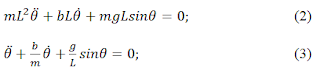
Let us put the above equations in ordinary differential equation form.

 We can assume any initial condition to solve the above ODEs. Let’s assume the following:


The position of Pendulum bob can be found out using simple trigonometric equations:


We will use above sets of equation to write our code and simulate the behavior of a simple harmonic oscillator and a non-linear pendulum.

Symbols used:

m= mass of the pendulum (neglecting mass of the hanging string)

L= Length of the string

b = damping coefficient

g = acceleration due to gravity = 9.81 m/s2

θ = angle subtended by the string with vertical position


LabVIEW implementation

Small initial angle; x1(0) = 25

The response of both linear (simple harmonic oscillator) and non-linear (Pendulum) system overlaps and identical. It holds true because for small θ, sinθ = θ. Thus equation (5) and (6) become same.


For large value of initial angle x1(0), the response of Linear and Non-linear pendulum varies as they have different angular displacements.


The “Damping enable” button allows us to enable or disable damping in our simulation.


Block Diagram of code


Tuesday, January 11, 2022

Micro second pulse train generation using Arduino

A very fast pulse train generator can be made using Arduino if we let go of the default instructions of Arduino IDE. The digitalWrite() command has inbuilt steps which makes the execution altogether slower. using this instruction we cannot achieve a pulse train faster than 150 kHz.

If we make changes at register level, pulses as fast as 4 MHz can be generated using Arduino UNO which houses a 16 MHz oscillator.

void setup(){

pinMode (13, OUTPUT);

}
void loop(){
while (1){ // this skips the loop() processing in the background
PORTB = 0b00100000; // write D13 (on Uno) to a 1
delayMicroseconds (5);// 5us delay, I believe it needs to be multiples of 4 on an Uno
PORTB = 0b11011111; // D13 to a 0
delayMicroseconds (20); // 20us delay
} // end while()
} // end loop()


The resulting pulse train from above code is shown. we can see there is jitter in the pulses. This is due to the instruction pinMode() which add problem with the code.

Let us make slight change in the code as below.

void setup(){
//pinMode (13, OUTPUT);

DDRB |= 0B00100000;
cli();
TIMSK0 &= ~(1 << TOIE0);
sei();

}
void loop(){
while (1){ // this skips the loop() processing in the background
PORTB = 0b00100000; // write D13 (on Uno) to a 1
delayMicroseconds (5);// 5us delay, I believe it needs to be multiples of 4 on an Uno
PORTB = 0b11011111; // D13 to a 0
delayMicroseconds (20); // 20us delay
} // end while()
} // end loop()


The resulting pulse train is stable even with lower pulse width and higher frequency. We can go for lower value of delay but the output pulse width will not be accurate as can be seen below. For the same code above where Ton is 5us, I am getting pulse width of 4us.

I could reach a pulse width of 60 ns for width set at 1us in code. This is interesting to get such a narrow pulse using a UNO though not accurate.The cause of this inaccuracy at lower pulse width is unknown to me.


Sunday, August 8, 2021

Sinusoidal wave generation using NI USB 6008

 National Instruments (NI) offers a wide range of data acquisition (DAQ) solutions to engineer and scientists since its inception. However a small time hobbyist may feel afraid to get one due to their high cost.

NI USB 6008/6009 offers a low cost alternative to hobbyist and college students. Its plug and play ability is convenient and offers less setup time.

In this post I will post the setup and code for generating sinusoidal waveform using analog output channel of USB6008.

Before that I must mention that analog output in USB 6008 is software timed. Software timed analog output means that your analog channel will update only once for every iteration of the program's while loop. It is important to remember that these devices allow a maximum update rate of 150 samples per second on each channel. Therefore the main program's while loop cannot iterate faster than once every 6 ms.

Secon important thing to keep in mind is that USB 6008 can output analog voltage in the range of 0...5VDC. So the output sinewave is not truly AC but a unipolar sinusoid. The code below will generate a sinusoid around 2.5 VDC offset.


On the front panel, we select the appropriate Physical channel, set the output rate and points per cycle to get the desired frequency of sinewave.


The output sine wave will have an approximate frequency = 1 / (output rate * points per cycle).  

Thursday, December 3, 2020

LabVIEW case structure: Making variables for inactive case invisible

 Hello,


Recently my friend gave me a situation where he need to build a case structure in LabVIEW such that the front panel display variables required in active/ selected case only.

This is actual problem that he gave me. Lets go ahead and see what I had done.

Case-1: Active variables "K" and "L"


Case-2: Active variables "h"


Case-3: Active variable "Sigma" and "F"

Lets us see the block diagram.

Case 1:

Case 2:


Case 3:


I have used visible property in property node for each variable in each case. Only the one need to show up is set TRUE and rest other are set FALSE.

I hope you like it.


Wednesday, September 2, 2020

Instrumentation Engineering Reference Books Subject wise

 MATHEMATICS

  1. Grewal B S: Higher Engineering Mathematics, Khanna Publishers
  2. Lipschutz S., and Lipson M.L.: Probability (Schaum's Outline Series), TMH
  3. Spiegel M.R. , Lipschutz S., John J.S., and Spellman D., : Complex Variables, TMH.
  4. Bhamra K. S.: Partial Differential Equations: An introductory treatment with applications, PHI
  5. Dutta Debashis: Textbook of Engineering Mathematics, New Age International Publishers.
  6. Kreyzig E.: Advanced Engineering Mathematics, John Wiley and Sons.
  7. Potter M.C, Goldberg J.L and Aboufadel E.F.: Advanced Engineering Mathematics, OUP.
  8. Ramana B.V.: Higher Engineering Mathematics, TMH. 
DIGITAL ELECTRONICS
  1. Morries Mano- Digital Logic Design- PHI
  2. R.P.Jain—Modern Digital Electronics, 2/e , Mc Graw Hill
  3. H.Taub & D.Shilling, Digital Integrated Electronics- Mc Graw Hill
  4. Tocci, Widmer, Moss- Digital Systems,9/e- Pearson
  5.  Floyed & Jain- Digital Fundamentals-Pearson
ANALOG ELECTRONICS
  1. Sedra & Smith-Microelectronic Circuits- Oxford UP
  2. Franco—Design with Operational Amplifiers & Analog Integrated Circuits , 3/e, McGraw Hill
  3. Boylested & Nashelsky- Electronic Devices and Circuit Theory- Pearson/PHI
  4. Millman & Halkias – Integrated El;ectronics, McGraw Hill.
  5. Malvino—Electronic Principles , 6/e , McGraw Hill
  6. Horowitz & Hill- The Art of Electronics; Cambridge University Press.
  7. Gayakwad R.A -- OpAmps and Linear IC’s, PHI
CIRCUIT THEORY AND NETWORKS
  1. Network Analysis, M.E.Van Valkenburg (Prentice Hall)
  2. Engineering Circuit Analysis, W.H.Hayt, J.E.Kenmerly, S.M.Durbin,(TMH)
  3. Network and Systems, D.Roychowdhury,(New Age International)
  4. Modern Netwok Analysis, F.M.Reza & S.Seely, McGraw Hill.
ELECTRICAL MEASUREMENTS & INSTRUMENTS
  1. Harris, F. K. – Electrical Measurements, Wiley.
  2. Sawhney A K : A course in Electrical & Electronic Measurements & Instruments, Dhanpat Rai & Co.
Sensors and Transducers
  1. D Patranabis, Sensors and Transducers, PHI, 2nd ed.
  2. E. A. Doebelin, Measurement Systems: Application and Design Mc Graw Hill, New York
  3. H. K. P. Neubert, Instrument Transducers, Oxford University Press, London and Calcutta 
PROCESS CONTROL
  1. D. Patranabis, Principles of Process Control, TMH, New Delhi, 2nd Ed.
  2. D. P. Eckman, Automatic Process control, John Wiley, New York
  3. P. Harriott, Process control, Mc Graw Hill, New York
  4. D. R. Coughanowr, Process Systems Analysis and Control, McGraw Hill 
  5. C. D. Johnson, Process Control Instrumentation Technology, PHI
  6. B. G. Liptak, Instrument Engineers Handbook, Chilton Book Co., Philadelphia

Modbus and OPC comparison Table

  Modbus vs OPC Comparison between Modbus and OPC Feature Modbus OPC (OLE f...